
Solar Array String Sizing Calculator For Pv Design
Size solar array strings by checking module voltage, temperature effects, and inverter limits. Review essential PV string-sizing calculations before final system design.
Please complete this field to continue.
Please complete this field to continue.
Please complete this field to continue.
Please complete this field to continue.
Please complete this field to continue.
Please complete this field to continue.
Please complete this field to continue.
Please complete this field to continue.
Please complete this field to continue.
Please complete this field to continue.
Results
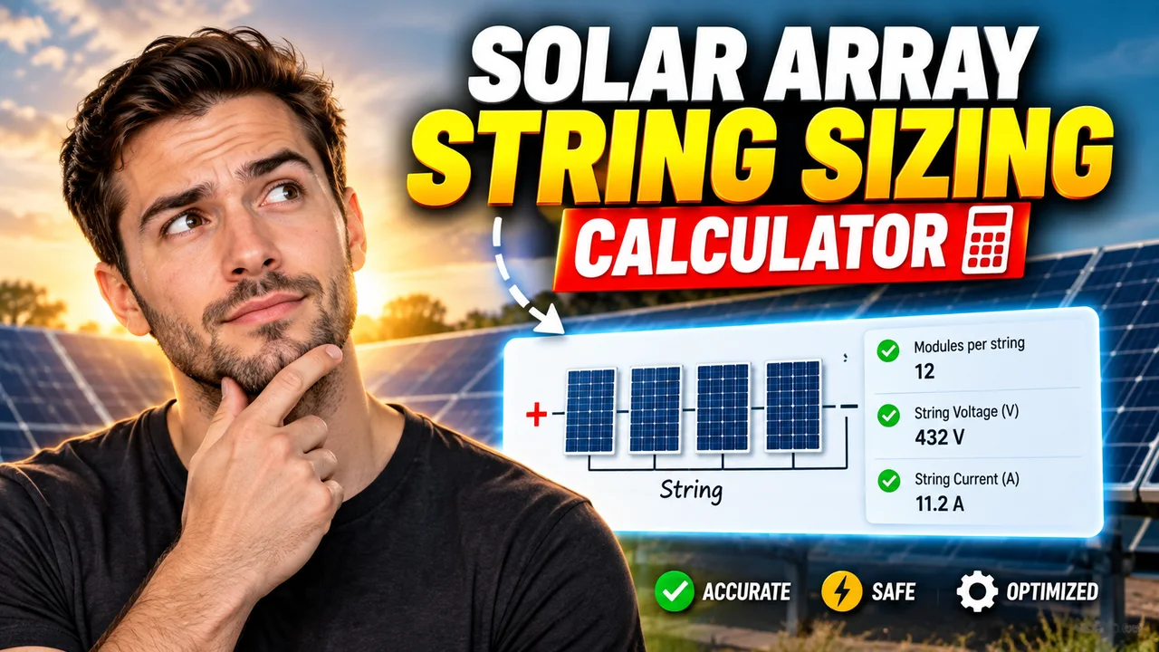
Solar Array String Sizing Calculator
Quick answer: The Solar Array String Sizing Calculator is an engineering calculator intended to help determine how many solar photovoltaic (PV) modules can be connected in series in a string while keeping the string voltage within an inverter's or charge controller's permitted operating range. String sizing requires module electrical specifications, inverter voltage limits, and temperature-dependent voltage adjustments.
The Solar Array String Sizing Calculator is designed for solar installers, PV system designers, electrical engineers, and solar energy students who need to evaluate series-connected solar panels. Correct string sizing helps ensure that the array's cold-weather open-circuit voltage does not exceed the equipment's maximum DC input voltage and that its operating voltage remains suitable for the inverter or charge controller.
Important: The tool's exact input fields, implemented formulas, and output format have not been independently established from the supplied tool name and image URL. The technical guidance below describes the standard engineering calculations relevant to PV string sizing; it should not be interpreted as confirmation of specific calculator features.
TL;DR / Key Takeaways
- Primary Function: Evaluate the number of PV modules that may be connected in series.
- Key Inputs: Module voltage specifications, equipment voltage limits, and relevant temperature data.
- Core Output: A calculated string-size range, when the required inputs and calculations are supported.
- Best Suited For: Preliminary PV system design and electrical compatibility checks.
How to Use Solar Array String Sizing Calculator?
- Identify the solar module: Obtain the module datasheet and locate open-circuit voltage (Voc), maximum-power-point voltage (Vmp), and the voltage temperature coefficient. Use the coefficient and units specified by the manufacturer.
- Identify the inverter or charge controller: Record the maximum permitted DC input voltage, MPPT operating-voltage range, and any applicable minimum startup or operating voltage.
- Establish design temperatures: Determine the applicable minimum cell temperature and expected maximum operating cell temperature using the project location, design criteria, and applicable electrical requirements.
- Calculate the allowable series count: Check the cold-corrected Voc against the equipment's maximum DC voltage and verify that the hot and cold operating voltages fit the equipment's permitted operating range.
These are the engineering steps for evaluating string size. The actual calculator interface may request different fields or use a different calculation workflow.
Solar Panel String Sizing: Inputs and Outputs
| Parameter | Meaning | Why It Matters |
|---|---|---|
| Module Voc | Open-circuit voltage of one panel, in volts | Used to check maximum string voltage, particularly in cold conditions. |
| Module Vmp | Voltage at the panel's maximum power point, in volts | Used to estimate string operating voltage. |
| Voc temperature coefficient | Change in Voc with temperature, usually expressed as %/°C or V/°C | Allows the panel's open-circuit voltage to be adjusted for design temperature. |
| Maximum DC input voltage | Highest permitted DC voltage at the inverter or controller input | Sets an upper limit on the series-connected module count. |
| MPPT voltage range | Equipment's permitted maximum-power-point tracking range | Helps determine whether the string can operate effectively across expected temperatures. |
| Design temperature | Relevant minimum or maximum temperature for the calculation | Cold temperatures generally raise Voc; high cell temperatures generally reduce operating voltage. |
| Series module count | Number of modules connected positive-to-negative in one series string | Determines the string's total voltage. |
Input and Output Example
The following is an illustrative engineering example, not a verified output from the supplied calculator.
Example module and equipment specifications
- Module open-circuit voltage (Voc): 49.5 V
- Module maximum-power-point voltage (Vmp): 41.5 V
- Voc temperature coefficient: −0.28%/°C
- Reference module temperature: 25°C
- Minimum design cell temperature: −10°C
- Maximum permitted inverter DC voltage: 600 V
Step 1: Calculate the temperature difference.
ΔT = 25 − (−10) = 35°C
Step 2: Estimate cold-corrected module Voc.
Cold Voc = 49.5 × [1 + (0.0028 × 35)]
Cold Voc = 49.5 × 1.098 = 54.351 V
Step 3: Calculate the voltage-based upper limit.
Maximum series count = floor(600 ÷ 54.351) = 11 modules
Illustrative result: Eleven modules produce an estimated cold open-circuit string voltage of 597.86 V, while twelve modules would produce approximately 652.21 V and exceed the assumed 600 V limit.
This example checks only the cold-voltage ceiling. Eleven modules are not automatically a valid final design: the inverter's MPPT range, startup voltage, module tolerances, applicable electrical codes, and other manufacturer requirements must also be checked.
Formula and Calculation Methodology
PV string sizing normally requires both an upper voltage limit and an operating-voltage compatibility check. The permissible series count is constrained by the most restrictive applicable condition.
1. Cold-corrected open-circuit voltage
When the manufacturer's Voc temperature coefficient is expressed as a negative percentage per degree Celsius, a simplified linear estimate is:
Voc,cold = Voc,STC × [1 + |βVoc| × (25 − Tmin)]
- Voc,cold: Estimated open-circuit voltage of one module at the minimum design cell temperature, in volts.
- Voc,STC: Module open-circuit voltage at standard test conditions, in volts.
- βVoc: Absolute fractional Voc temperature coefficient per °C. Convert a percentage to a decimal before calculation.
- Tmin: Minimum design cell temperature, in °C.
If the coefficient is provided in volts per degree Celsius rather than as a percentage, use a compatible voltage-based expression instead. Follow the module manufacturer's stated coefficient convention and any required correction method.
2. Maximum series module count
Nmax = floor(VDC,max ÷ Voc,cold)
Here, VDC,max is the maximum permitted DC input voltage of the connected equipment. The floor function rounds down to the nearest whole module because a series string cannot contain a fraction of a module.
3. Operating-voltage check
At a given condition, a first-order estimate of string operating voltage is:
Vstring,mp ≈ N × Vmp,module
The actual maximum-power-point voltage varies with cell temperature and irradiance. A complete design checks the corrected string operating voltage against the manufacturer's MPPT range at relevant temperature extremes and verifies any minimum startup voltage separately.
Solar String Sizing Reference Table
| Check | Calculation or Comparison | Design Requirement |
|---|---|---|
| Cold open-circuit voltage | N × Voc,cold | Must not exceed the equipment's maximum permitted DC voltage. |
| Nominal operating voltage | N × Vmp,module | Provides an initial estimate; temperature correction is needed for design verification. |
| Hot operating voltage | N × Vmp,hot | Must remain compatible with the minimum MPPT or operating voltage requirement. |
| Cold operating voltage | N × Vmp,cold | Must remain compatible with the equipment's maximum MPPT voltage, where applicable. |
| Whole-module constraint | Integer N ≥ 1 | The final series count must be a positive whole number. |
| Equipment compatibility | Compare all calculated values with datasheet limits | Use the most restrictive applicable voltage condition. |
Edge Cases and Limitations
- Cold-weather overvoltage: A string that is below the inverter limit at 25°C can exceed it on a cold morning because module Voc rises as temperature falls.
- Hot-weather undervoltage: A string that meets the maximum-voltage check may still operate below the MPPT minimum in hot conditions.
- Temperature coefficient units: Confusing −0.28%/°C with −0.28 as a fractional value creates a substantial calculation error.
- Reference temperature: The simplified Voc equation assumes the reference value corresponds to 25°C. Use the correct reference conditions for the supplied datasheet.
- Extreme temperatures: A linear temperature-coefficient estimate may not represent every module's behavior across all conditions. Follow manufacturer guidance and applicable design requirements.
- Multiple MPPT inputs: Different string configurations or inverter inputs may have separate voltage and current restrictions.
- Current and parallel strings: Series-string voltage calculations do not establish that input current, parallel-string count, conductor ampacity, overcurrent protection, or connector ratings are acceptable.
- Missing or inconsistent data: Do not finalize a design if module coefficients, equipment limits, or design temperatures are unknown or use incompatible units.
Engineering References
Use manufacturer documentation and applicable electrical requirements to verify the assumptions used in a string-sizing calculation. Relevant starting points include the National Renewable Energy Laboratory's photovoltaic research resources and the U.S. Department of Energy Solar Energy Technologies Office.
Technical Disclaimer: This content describes preliminary PV string-sizing methodology. The example is illustrative and does not establish the suitability of a real installation. Confirm voltage, current, temperature, protection, equipment, and jurisdictional requirements with current manufacturer datasheets, applicable electrical codes, and a qualified solar electrical professional before installation or energization.
Author: Daniel Brooks
Author Description: Electrical Engineer specializing in photovoltaic system design and DC power-system engineering.
Technical Review: The calculation methodology should be checked against module temperature coefficients, inverter voltage limits, site-specific design temperatures, and the applicable electrical installation requirements before it is used for a real PV system.
